The RFID Smart Door Lock is a functional prototype that replaces traditional mechanical keys with contactless RFID authentication. It addresses a common frustration: getting locked out when you forget your keys. The system uses a stepper motor to physically turn the key, controlled by an Arduino that verifies RFID cards.
Project Goal: Build a keyless entry system that integrates with existing door hardware, supports multiple users, and provides visual feedback—without requiring permanent modifications to the door.
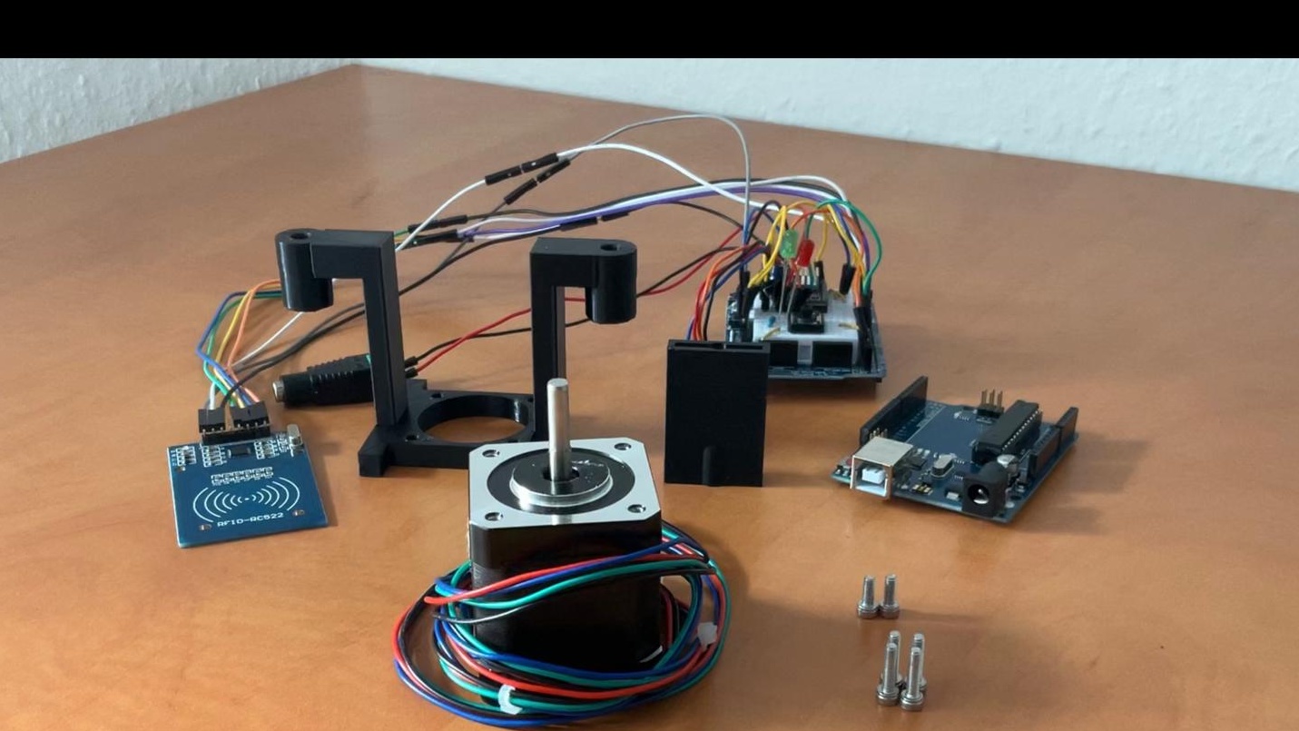
Technical Overview
| Component | Details |
|---|---|
| Microcontroller | Arduino Uno R3 |
| Motor | NEMA 17HS19 Stepper Motor |
| Authentication | RC522 RFID Reader (13.56MHz) |
| Motor Driver | DRV8825 with current limiting |
| Power Supply | 12V 1.5A external PSU |
| Fabrication | Custom 3D-printed mount (PLA, Ender 3 V2) |
| Status Display | Red/Green LED indicators |
Key Features
- RFID Authentication: Supports multiple authorized card IDs stored in firmware. Easy to add guest access by lending a registered card.
- Full Lock Control: The stepper motor provides 400+ steps of rotation, enabling both single and double locking positions.
- Visual Feedback: Green LED for unlocked state, red LED for locked state, with blinking during motor movement.
- Manual Override: Physical button on the inside for lock/unlock without RFID card.
- Non-Destructive Install: Mounts using existing lock cover screw holes—no permanent door modifications required.
Design & Fabrication
The mechanical design was created in Autodesk Fusion 360 and printed in PLA. The mount serves three critical functions:
- Motor alignment: Holds the stepper motor at the precise distance and angle to engage the key.
- Arduino housing: Integrated mounting points for the microcontroller with melted-in threaded inserts for secure fastening.
- Existing hardware compatibility: Uses the original lock cover mounting holes for tool-free installation.
The key holder attachment was designed to grip standard house keys and rotate with the motor shaft. Multiple iterations were needed to achieve the right balance between grip strength and ease of installation.
Embedded Software
The Arduino code uses three main libraries:
- AccelStepper: Provides smooth motor acceleration/deceleration with position tracking.
- MFRC522: Handles RFID card reading and UID extraction.
- SPI: Communication protocol for the RFID reader.
Core Logic Flow
Loop Cycle:
├── card(): Check for RFID card presence
│   └── If authorized → openLock()
├── motor(): Execute movement to target position
│   ├── Track current vs. target position
│   └── Auto-return after reaching unlock position
├── led(): Update status indicators based on lock state
└── button(): Handle manual lock/unlock from interior
Motor Control Precision
The DRV8825 driver requires current limiting to prevent thermal issues and ensure consistent torque. I calibrated the driver to a 1V reference using a multimeter on the potentiometer test point, which reduced motor skipping and prevented driver overheating.
Position tracking uses step counting rather than absolute position sensing. This means it can drift if steps are missed and may require re-homing after startup, which is a known limitation addressed in the reflection below.
Engineering Challenges
Torque Requirements
The NEMA 17 motor was barely strong enough to turn the lock mechanism. Under certain conditions (cold weather, tight lock alignment), the motor would skip steps. This taught me the importance of proper motor sizing and the potential need for gear reduction to trade speed for torque.
State Management Without Sensors
Because the system uses step counting rather than absolute encoders or limit switches, any mechanical slip (skipped steps) causes the tracking to drift out of calibration. A production version would benefit from Hall effect sensors or optical encoders to detect actual lock position.
Power Supply Trade-offs
Using an external 12V power supply was pragmatic for the prototype but limits real-world deployment. The next iteration would use a rechargeable Li-ion battery pack with a charging circuit, similar to commercial smart locks like Nuki.
Market Comparison
Commercial solutions like the Nuki Smart Lock (€280) offer:
- Bluetooth app control with auto-unlock proximity detection
- 6-month battery life with quick recharge
- End-to-end encryption
- Integration with smart home ecosystems (Alexa, Google Home)
This project demonstrates that the core mechanical and authentication functionality can be replicated with off-the-shelf components for under €50 in parts. The gap to commercial products lies primarily in:
- Polish (battery operation, encrypted communication, mobile app)
- Reliability (stronger motors, position feedback)
- UX (LCD display, audit logging, remote access)
What I Learned
Technical Growth
- Stepper motor control: Current limiting, microstepping, and the importance of matching motor specs to mechanical load.
- Embedded state machines: Managing multiple concurrent functions (motor movement, LED blinking, card reading) without blocking delays.
- 3D CAD for functional parts: Designing for printability, tolerances, and integrating threaded inserts.
Systems Thinking
- Failure mode analysis: Understanding that skipped steps can’t be detected without additional sensors.
- Power budgeting: Calculating runtime vs. battery capacity for mobile applications.
- User experience: Even technically functional systems need visual feedback and error handling to be usable.
Future Improvements
If I were to build version 2.0:
- Gear reduction system: 3D-printed planetary gearbox to increase torque 3-5x, eliminating skipped steps.
- Absolute position sensing: Magnetic encoder or limit switches to auto-calibrate on startup.
- Battery operation: 18650 Li-ion cells with TP4056 charging module and low-voltage cutoff.
- LCD menu system: OLED display with rotary encoder for adding/removing RFID cards without reprogramming.
- Access logging: Real-time clock (DS3231) plus SD card to log all unlock events with timestamps.
- Fallback mechanism: Clutch system that allows manual key operation if electronics fail.
Conclusion
This project successfully demonstrates that complex commercial products can be reverse-engineered and prototyped with hobbyist tools. While not production-ready, it validates the core concept and provides a foundation for understanding the engineering trade-offs in smart home security devices.
The honest assessment of its limitations—motor torque, power delivery, position tracking—reflects the reality that first prototypes reveal problems that need solving. That’s exactly what makes hardware projects valuable learning experiences.
Most importantly: it works. The door unlocks when you tap an authorized RFID card, and it locks when you press the button. Everything else is iteration.